Step-by-Step User Report: Surgical Procedure
Step-by-Step User Report
– Surgical Procedure
User Report by Freddi Zelener, MSc, Berlin
Specialist Dentist in Oral Surgery, Master of Science in Implantology
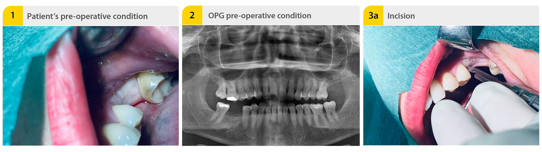
1. Patient’s pre-operative condition
Extraction with sufficient volume of tooth 46 at a family dentist 4 months ago. A healed alveolar ridge with sufficient volume was clinically visible. However, X-rays showed an alveolus that was not completely ossified.
2. OPG pre-operative condition
In spite of low bone quality, a sufficient primary stability could be achieved due to the implant’s macrostructure. During bone preparation, the drilling sequence depends on the quality of the bone. The lesser the quality, the lower the preparation of the bone.
3a. Incision
Mid-crestal incision.
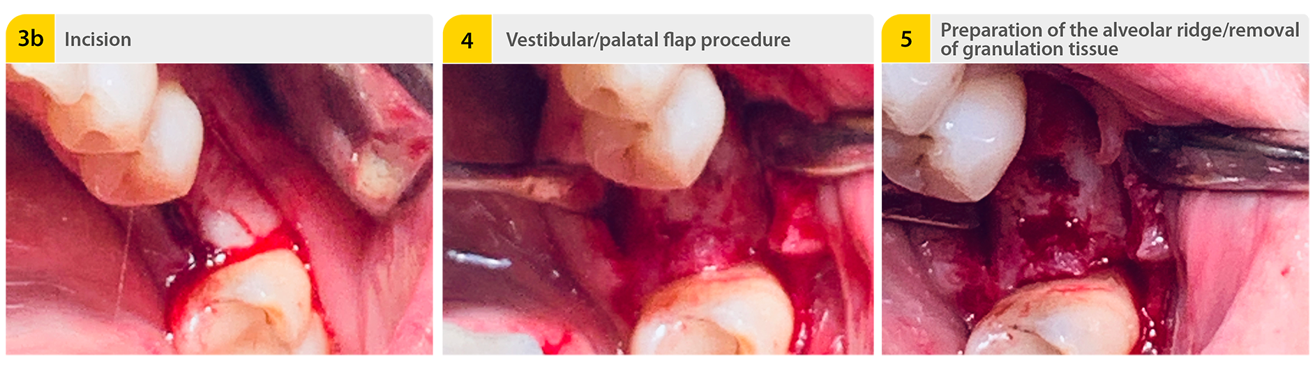
3b. Incision
4. Vestibular/palatal flap procedure
5. Preparation of the alveolar ridge/removal of granulation tissue
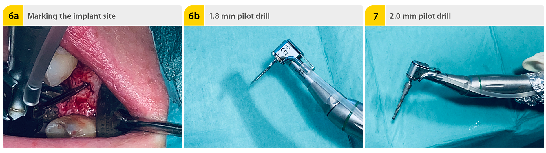
6a. Marking the implant site
The 1.8 mm pilot drill is used to mark the implant site determined during planning of the implant position. The speed setting is 800 rpm.
6b. 1.8 mm pilot drill
7. 2.0 mm pilot drill
The pilot hole is created with the 2.0 mm pilot drill up to a depth of about 6.5 mm.
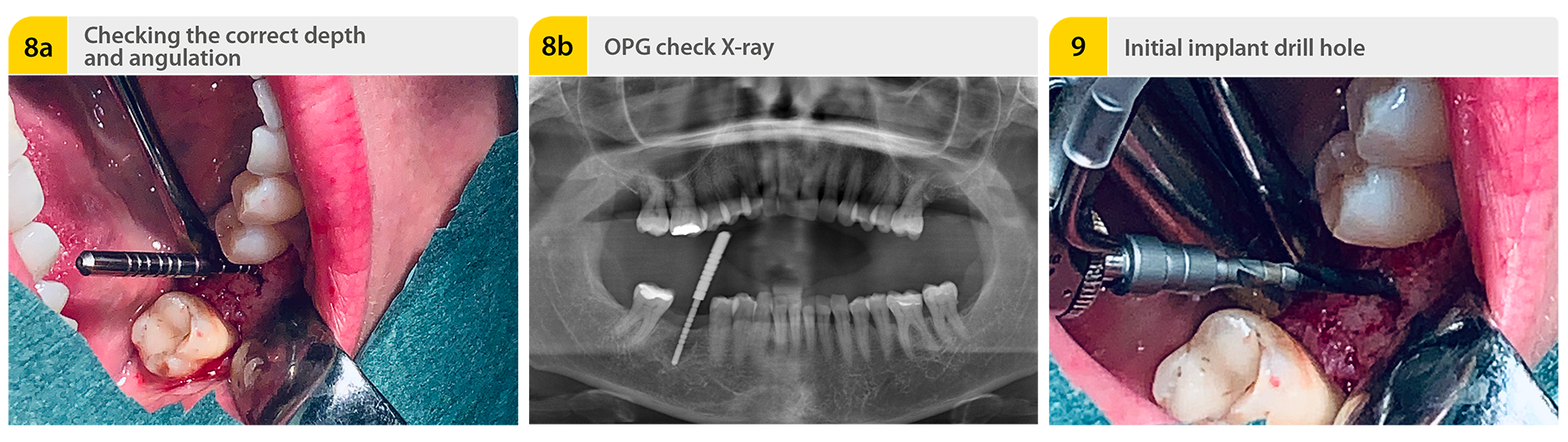
8a. Checking the correct depth and angulation
Paralleling aid in the implant site. The paralleling aid is then used to check the correct implant axis.
8b. OPG check X-ray
An X-ray is taken to check the relationships to the anatomical structures, especially in the case of a reduced vertical bone supply. For that, the paralleling aid is inserted into the implant site.
9. Initial implant drill hole
2.0 mm pilot drill with the final drilling depth. Next, the 2.0 mm pilot drill is used to extend the implant site to the final preparation depth. The preparation depth is checked with the depth gage.
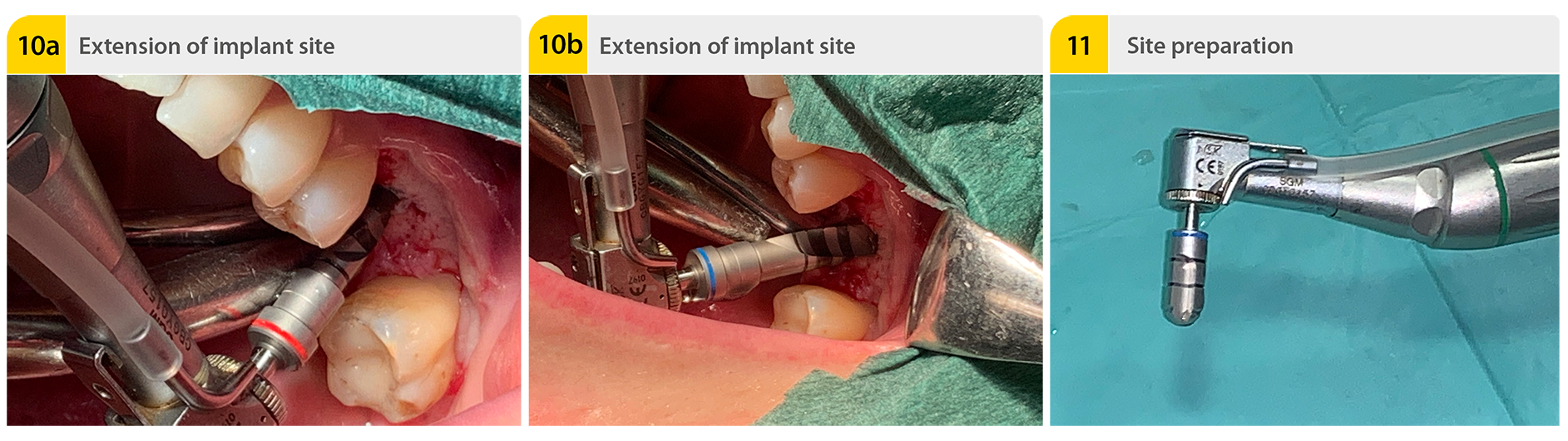
10a. Extension of implant site
The implant site is extended to the final preparation diameter with the extension drills. The depth gage is again used to check the preparation depth.
10b. Extension of implant site
According speed settings for each diameter: Ø 2.75 mm - 700 rpm, Ø 3.0 mm and Ø 3.4 mm - 500 rpm, Ø 3.7 mm, Ø 3.9 mm, Ø 4.25 mm, Ø 4.9 mm and Ø 5.25 mm - 400 rpm.
11. Site preparation
In the case of solid bone, the coronal part of the implant site is finished with the countersink. At this juncture, the countersink is introduced into the borehole in accordance with the bone conditions. In the course of this, the marks on the countersink must be observed. The countersink should be used to make a gentle, non-traumatic insertion of the implant with the lowest possible torque (30 Ncm max.) possible. The speed setting is 400 rpm.
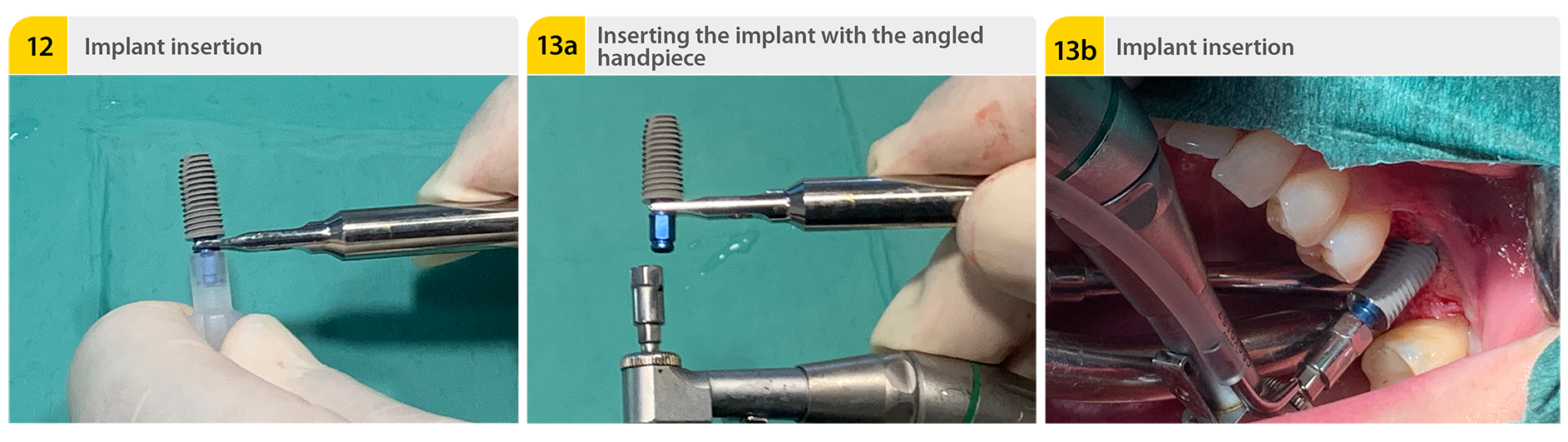
12. Implant insertion
The implant is inserted into the cavity with the aid of the implant carrier after removal of the sterile packaging. The implant can be inserted manually with the insertion key and ratchet drill or alternatively the insertion can be done with the angled handpiece.
13a. Inserting the implant with the angled handpiece
13b. Implant insertion
The implant is inserted in its final position at the bone level with slow rotations.
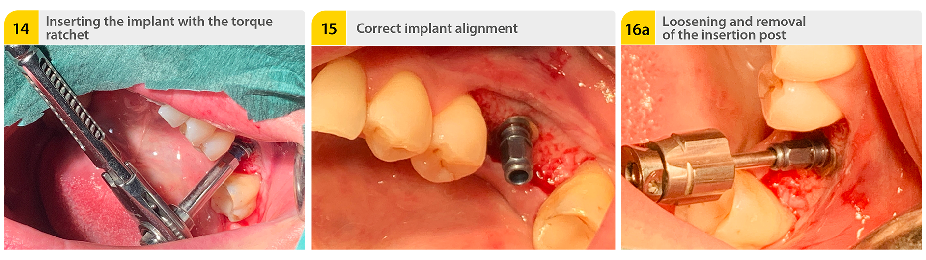
14. Inserting the implant with the torque ratchet
The implant is inserted in its final position at the bone level with slow ratchet twists. The maximum torque of 30 Ncm must be observed here.
15. Correct implant alignment
For optimal subsequent placement of the prosthesis on the implant, a correct implant alignment is important.
16a+b. Loosening and removal of the insertion post
The insertion post is removed from the implant after the fastening screw has been loosened. For this, the counterratchet can also be used when necessary.
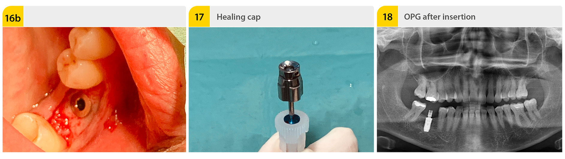
17. Healing cap
The inserted implant is sealed with the covering and healing cap located in the base of the implant carrier. The primary wound closure ends the implantation procedure. Based on my experience, the healing times must be observed for a successful implantation.
18. OPG after insertion
Freddi Zelener, MSc.
Freddi Zelener has more than twelve years of experience in implantology and is well regarded throughout Europe as a specialist in this field. In difficult cases, colleagues bring him in as a consultant and mobile operator, and trust in his expertise. Even the most complex operations are routine for him.

Download this case study as PDF file:
Read now!Please note:This report is not intended as an instruction manual. The instructions for the materials and appliances used must be observed. The responsibility lies with the attending dentist.


Tactile scans ... are worth the effort!

Bleaching with "Bleach’n Smile“

Case study: Cervical Fillings with PrimeBond7 and Capo Slow Flow
